
Install Types
IN DUCT INSTALL TYPE
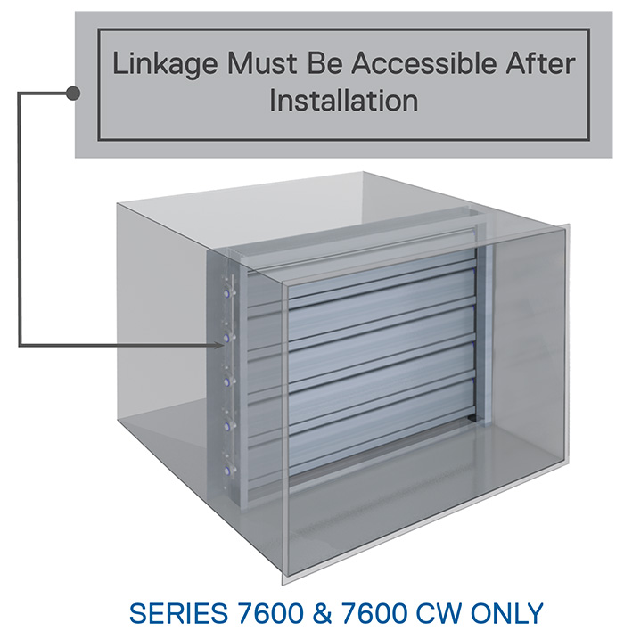
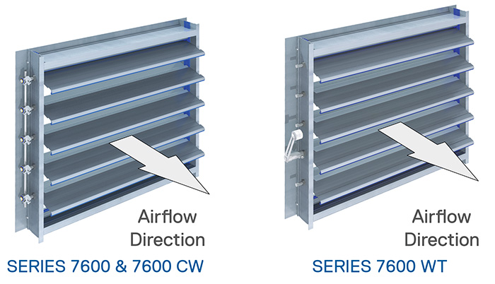
- Applies to Series 7600 and 7600 CW only. Series 7600 WT and 7600 CWA cannot be installed in a duct or opening, because the operation of the adjustable external weights or counterweights would be impeded.
- Backdraft damper is manufactured so that finished O.D. is ½” (12.7 mm) smaller than opening width and height dimensions.
- Verify that damper is square.
- Ensure that duct is square and/or large enough to allow damper to be installed square.
- Bottom of frame must sit flat on floor of duct to prevent twisting, sagging, or bowing.
- Secure bottom frame to floor of duct using a 90° mounting angle.
- As each mounting angle is installed, verify operation to ensure damper blades move freely are sealing correctly.
- Caulk all connections/joints between damper frame and duct to minimize installation leakage.
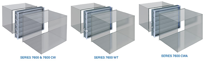
FLANGED TO DUCT INSTALL TYPE
- Applies to all Heavy-Duty Backdraft Damper Series.
- Front and rear damper flanges are 1” (25.4 mm) larger than duct or opening, around entire perimeter.
- Backdraft damper is manufactured so that finished O.D. is 2” (50.8 mm) greater than opening width and height dimensions.
- Verify that damper is square.
- Do not assume that duct is square. Verify that duct flange is square, flat and, even.
- Fasten damper to duct.
- Operate damper manually to verify free movement of blades and correct sealing.
- Re-verify that damper is square.
- Repeat procedure for other flange, if ducted on both sides.
- Caulk all connections/joints between damper frame and duct to minimize installation leakage.
EXTENDED FRONT FLANGE INSTALL TYPE
- Applies to Series 7600, 7600 CW, and 7600 WT only. Series 7600 CWA cannot be installed as Extended Front Flange type, because the extended flange at the front of the damper would impede operation of the adjustable external counterweight.
- Front damper flange is 2” (50.8 mm) larger than duct or opening, around entire perimeter, thereby providing a larger fastening surface.
- Rear damper flange is 1” (25.4 mm) larger than duct or opening, around entire perimeter. (Note that Extended Front Flange Install Type dampers are not designed so that the rear of the damper may be inserted into an opening, as the side frame members extend to the full height of the rear flange.)
- Backdraft damper is manufactured so that finished O.D. is 4” (101.6 mm) greater than opening width and height dimensions.
- Verify that damper is square.
- Do not assume that opening is square. Verify that opening or duct flange is square, flat, and even.
- Fasten damper to opening surface or duct.
- Operate damper manually to verify free movement of blades and correct sealing.
- Re-verify that damper is square.
- Repeat procedure for other flange, if ducted on both sides.
- Caulk all connections/joints between damper frame and opening or duct to minimize installation leakage.
EXTENDED REAR FLANGE INSTALL TYPE
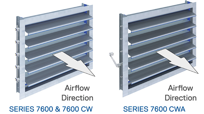
- Applies to Series 7600, 7600 CW, and 7600 CWA only. Series 7600 WT cannot be installed as Extended Rear Flange type, because the extended flange at the rear of the damper would impede operation of the adjustable external weight.
- Rear damper flange is 2” (50.8 mm) larger than duct or opening, around entire perimeter, thereby providing a larger fastening surface.
- Front damper flange is 1” (25.4 mm) larger than duct or opening, around entire perimeter. (Note that Extended Rear Flange Install Type dampers are not designed so that the front of the damper may be inserted into an opening, as the side frame members extend to the full height of the rear flange.)
- Backdraft damper is manufactured so that finished O.D. is 4” (101.6 mm) greater than opening width and height dimensions.
- Verify that damper is square.
- Do not assume that opening is square. Verify that opening or duct flange is square, flat, and even.
- Fasten damper to opening surface or duct.
- Operate damper manually to verify free movement of blades and correct sealing.
- Re-verify that damper is square.
- Repeat procedure for other flange, if ducted on both sides.
- Caulk all connections/joints between damper frame and opening or duct to minimize installation leakage.
- Documents