
Multi-Section Assemblies
Medium-Duty Backdraft Dampers
STRUCTURAL SUPPORT REQUIREMENTS:
- Field-supplied, intermediate structural support is required to resist applied velocity and pressure loads for backdraft dampers that are two or more sections high or wide.
- Angle bracing installed at multi-section joints will prevent bowing and twisting of backdraft damper units.
- TAMCO Series 7000 Backdraft Dampers weigh approximately 2 lbs/ft² (9.76 kg/m²). TAMCO Series 7000 WT and 7000 CW Backdraft Dampers weigh approximately 3 lbs/ft² (14.65 kg/m²).
MULTI-SECTION BACKDRAFT DAMPER ASSEMBLIES:
- Sections may be installed in or over its own field-supplied support structure individually, or they may be field-assembled prior to installation.
- If field-assembly is required before installation, lay dampers on a flat surface (such as a floor) with TAMCO label facing upwards to assemble sections.
- T-Bars provided by TAMCO to interconnect damper sections are for alignment purposes only and may not be considered as structural supports.
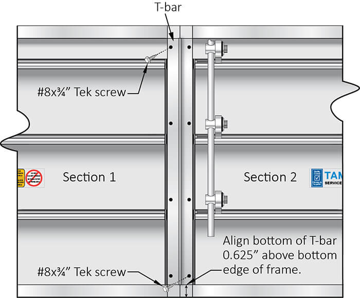
TWO OR MORE SECTIONS WIDE
- Ensure that all backdraft damper sections are straight, even, and aligned with each other.
- T-bars are to be installed on the back (sticker) side of the damper.
- To pierce alignment holes in the damper frames where the two section meet, apply the T-bar extrusion so that it sits 0.625″ (16 mm) above the bottom edge of the vertical frames where backdraft damper sections meet. Verify that the T-bar sits flat against each damper frame and is flush to the side of each frame member, so it does not interfere with blade operation.
- Secure the T-bar to Section 2 through the lowest right hole in the T-bar, using a #8x¾” Tek screw. Next secure the T-bar to the Section 1 through the uppermost left hole in the T-bar, using a #8x¾” Tek screw. This will ensure proper alignment of two horizontally joining sections, once the T-bar is fully installed.
- If leakage is a concern, now remove the T-Bar and apply a bead of silicone caulk along the joint where the two damper frames meet. Then, replace the T-Bar and the two screws, using the alignment holes made previously.
- Finish securing the T-Bar to the damper frames by inserting #8x¾” Tek screws into the rest of the holes located on the T-Bar.
- Repeat the steps listed above for any additional sections that are connected horizontally.
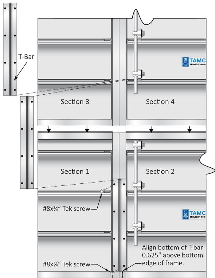
MULTIPLE SECTIONS WIDE BY MULTIPLE SECTIONS HIGH
- Ensure that all backdraft damper sections are straight, even, and aligned with each other.
- Install the bottommost sections of the backdraft damper assembly first.
- T-bars are to be installed on the back (sticker) side of the damper. Each T-bar will be shorter than the height of a single section. This is to ensure that a full T-bar piece can be centered across the intersection where four damper sections meet.
- To pierce alignment holes in the damper frames where the two section meet, apply the T-bar extrusion so that it sits 0.625″ (16 mm)
- above the bottommost edge of the vertical frames where backdraft damper sections meet. Verify that the T-bar sits flat against each damper frame and is flush to the side of each frame member, so it does not interfere with blade operation.
- Secure the T-bar to Section 2 through the lowest right hole in the T-bar, using a #8x¾” Tek screw. Next secure the T-bar to the Section 1 through the uppermost left hole in the T-bar, using a #8x¾” Tek screw. This will ensure proper alignment of two horizontally joining sections, once the T-bar is fully installed.
- If leakage is a concern, now remove the T-Bar and apply a bead of silicone caulk along the joint where the two damper frames meet. Then, replace the T-Bar and the two screws, using the alignment holes made previously.
- Finish securing the T-Bar to the damper frames by inserting #8x¾” Tek screws into the rest of the holes located on the T-Bar.
- Repeat the steps listed above for any additional sections that are connected horizontally.
- Install the next row of dampers. Stack the next T-Bar directly above the previously fastened one, and repeat the steps above for all subsequent backdraft damper sections, until the full height of the damper is connected with T-Bars.
- Documents